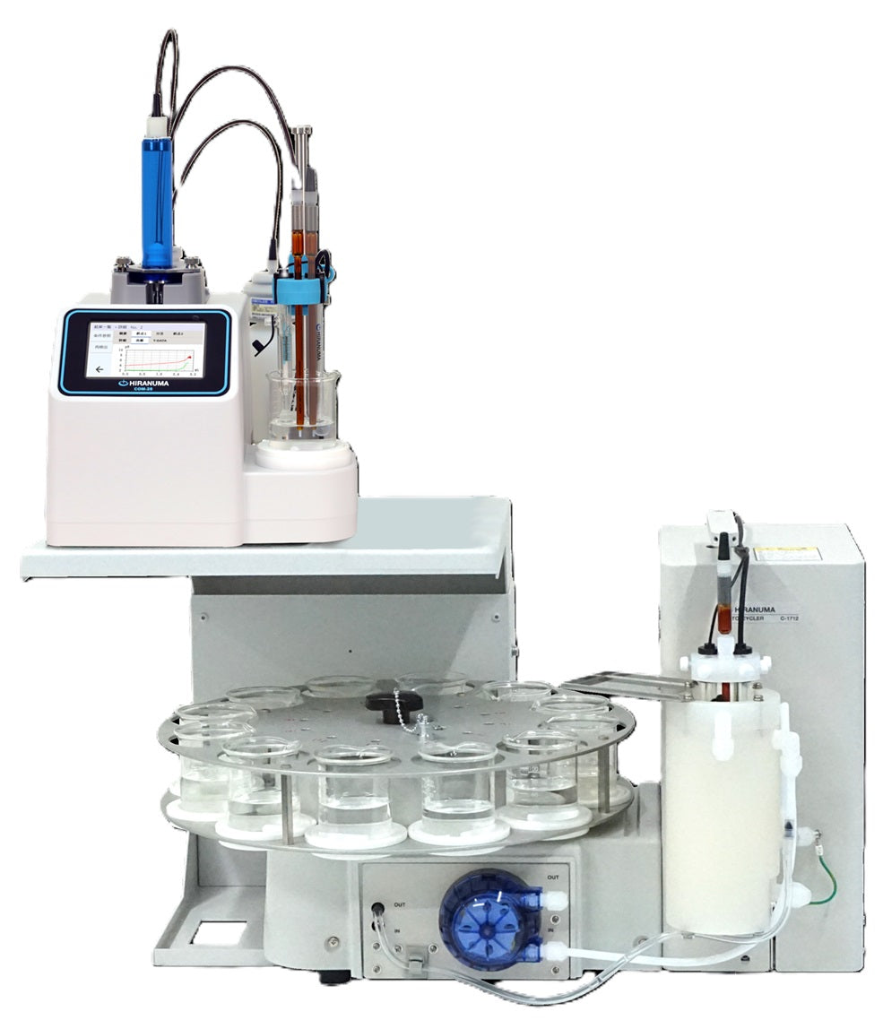
| HIRANUMA APPLICATION DATA | Karl Fischer Titrator | Data No. | KF4 | Jun.6. 2017 |
| Water contents | Oil products |
1. Abstract
Water content of Oil products are determined by Karl Fischer coulometric titrator. In coulometric titration, iodine of Karl Fischer reagent is generated by electrolysis and generated iodine quantitatively reacts with water. Reaction formula is described below.
H₂O + I₂ + SO₂ + 3RN + CH₃OH → 2RN・HI + RN・HSO₄CH₃
2RN・HI → I₂ + 2RN + 2H⁺ + 2e⁻
Kerosene and diesel oil do not interfere the Karl Fischer reaction and direct injection method could apply. Anode solution for Oil is selected to dissolve samples.
It is known that some of the oil additives interfere Karl Fischer reaction. In that case, azeotropic distillation method with Oil evaporator is appropriate. Water is separated from oil sample by distillation and introduced to electrolytic cell with carrier gas.
Mercaptanes and hydrogen sulfide in oil interfere Karl Fischer reaction. Since these side reactions occur quantitatively, water content result could be corrected with concentration of mercaptanes and hydrogen sulfide. 1 ppm of mercaptanes or hydrogen sulfide lead 0.3 ppm or 0.6 ppm higher water content respectively.
2. Apparatus and Reagents
| (1) | Apparatus | ||
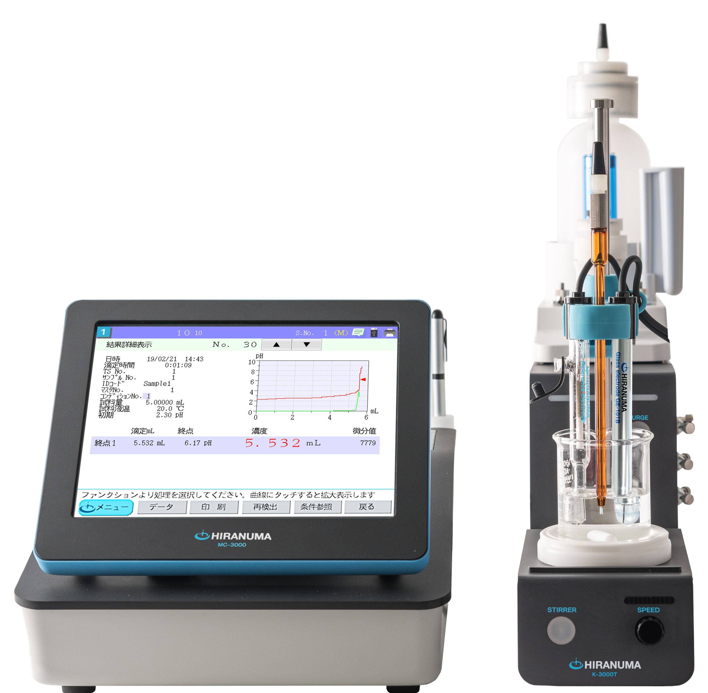
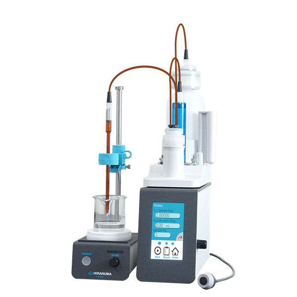
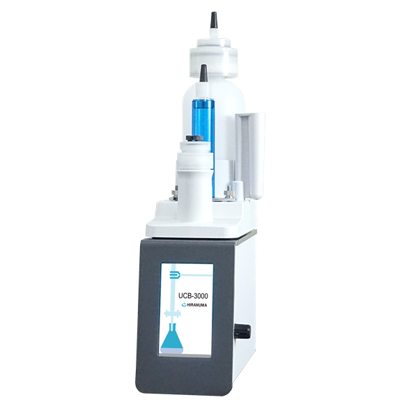
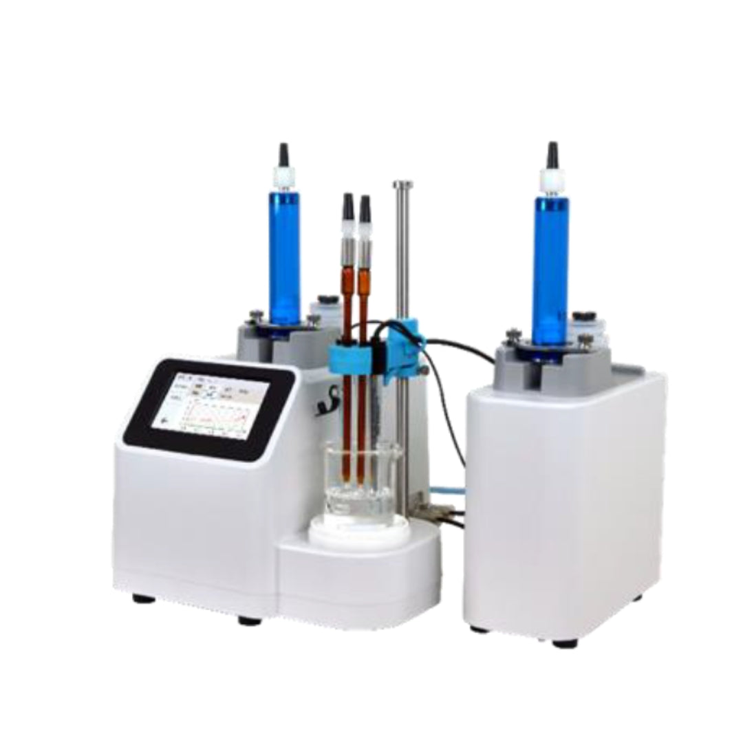
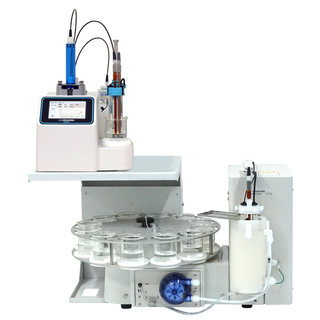
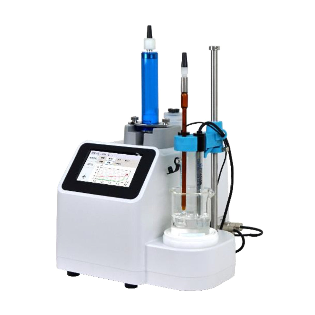
| Titrator | : | HIRANUMA Karl Fischer Coulometric titrator AQ-series or MOICO-A19 | |
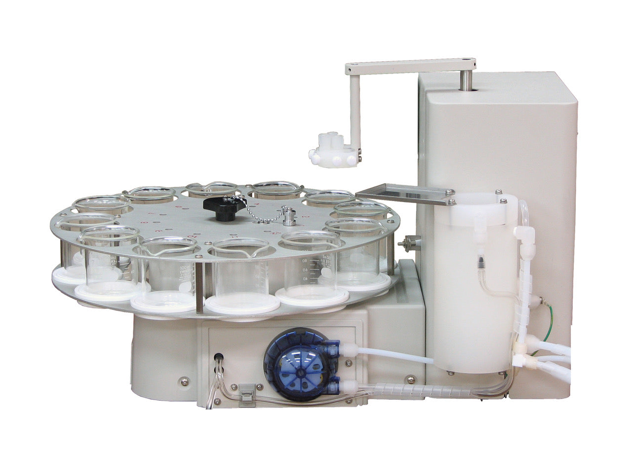
| Evaporator | : | Oil Evaporator EV-2000L | |
| Electrolytic cell | : | Standard Cell Fritless Cell |
|
| (2) | Reagents for direct injection method | ||
| Anode solution | : | Hydranal coulomat AG-H (for Oil, nonhalogenated) | |
| Cathode solution | : | Hydranal coulomat CG | |
| (3) | Reagents for azeotropic distillation method | ||
| Anode solution | : | Hydranal coulomat AG (for general use, nonhalogenated) | |
| Cathode solution | : | Hydranal coulomat CG | |
| Distillation solvemt | : | Dehydrated toluene | |
| Carrier gas | : | Nitrogen gas | |
3. Procedure
3.1. Direct injection method
| (1) | Fill 100 mL of anode solution and one ampoule of cathode solution into the electrolytic cell as shown in Fig.3.1. |
| (2) | Start blanking to attain stable background. |
| (3) | Wash the syringe with sample. |
| (4) | Draw the sample into syringe and then weigh the syringe. |
| (5) | Inject sample from rubber septum of electrolytic cell as shown in Fig.3.2. |
| (6) | Start titration. Measurement parameter is shown in Table 4.1. |
| (7) | Weigh the syringe again and then set the difference of weight to sample size. |

Fig.3.1. Preparation of the reagents.

Fig.3.2. Injection of sample.
3.2. Azeotropic distillation method
| (1) | Fill 100 mL of anode solution and one ampoule of cathode solution into the electrolytic cell as shown in Fig.3.1. |
| (2) | Start blanking to attain stable background. |
| (3) | Connect electrolytic cell and evaporation chamber with tube. Flow carrier gas with 50 mL/min. |
| (4) | Fill 5mL of distillation solvent in evaporation chamber and heat the chamber at 120 ℃. |
| (5) | Keep blanking to attain stable background with carrier gas flowing into electrolytic cell. |
| (6) | Wash the syringe with sample. |
| (7) | Draw the sample into syringe and then weigh the syringe. |
| (8) | Inject sample from rubber septum of distillation chamber as shown in Fig.3.3 and Fig.3.4. |
| (9) | Start titration. Measurement parameter is shown in Table 4.2. |
| (10) | Weigh the syringe again and then set the difference of weight to sample size. |

Fig.3.3. Schematic diagram of azeotropic distillation method.

Fig.3.4. Sample injection into evaporation chamber.
4. Parameters and results
Table 4.1. Parameters for direct injection method.
| Condition File | ||
| Cal Mode | 0:Sample weight(net) | |
| X=(H₂O-BLANK)/SIZE | ||
| Interval Time | 20 | sec |
| Current | SLOW | |
| S-Timer | 0 | min |
| Blank Value | 0 | ug |
| Unit Mode | AUTO | |
| Auto Interval | 0 | g |
| Minimum Count | 5 | ug |
| Back Ground | ON | |
| Sample Size Input | Every Time | |
| Cell Type | Standard/Fritless |
Table 4.2. Parameters for azeotropic distillation method.
| Condition File | ||
| Cal Mode | 0:Sample weight(net) | |
| X=(H₂O-BLANK)/SIZE | ||
| Interval Time | 40 | sec |
| Current | SLOW | |
| Min.Timer | 5 | min |
| Blank Value | 0 | ug |
| Unit Mode | AUTO | |
| Auto Interval | 0 | g |
| Minimum Count | 5 | ug |
| Back Ground | ON | |
| Sample Size Input | Every Time | |
| Cell Type | Standard/Fritless |
Table 4.3. Results of water content measurement in Oil products
| Sample | Apparatus | Cell | Reagent | Sample Size (g) |
Water (μg) |
Water Content |
| kerosene | AQ | Standard | AG-H | 2.3483 | 65.5 | 27.9 ppm |
| CG | 2.3482 | 61.5 | 26.2 | |||
| 2.4432 | 63.5 | 26.0 | ||||
| diesel oil | AQ | Standard | AG-H | 2.0817 | 72.7 | 34.9 ppm |
| CG | 1.9804 | 68.4 | 34.5 | |||
| 2.0600 | 70.4 | 34.2 | ||||
Table 4.4. Results of water content measurement in Oil products
| Sample | Apparatus | Cell | Reagent | Sample Size (g) |
Water (μg) |
Water Content |
| Biodiesel | AQ | Standard | AG-H | 0.9719 | 977.9 | 0.1006 % |
| CG | 0.9108 | 914.9 | 0.1005 | |||
| 0.8408 | 839.2 | 0.0998 | ||||
| Transmission | AQ+EV-L | Standard | AG | 0.7267 | 246.6 | 339.3 ppm |
| fluid | CG | 0.9484 | 329.1 | 347.0 | ||
| 0.9051 | 311.9 | 344.6 | ||||
| Fritless | AG | 0.8201 | 300.4 | 366.3 ppm | ||
| 0.8152 | 289.4 | 355.0 | ||||
| 0.9452 | 330.4 | 349.6 |
5. Note
| (1) | Use dried syringe and syringe vial for preventive of contamination by atmospheric water. |
| (2) | To measure 100 µg or less water detection, make sure stability of blanking. Low and stable background value is important factor for trace level of water measurement. |
| (3) | Put appropriate anode solution in use according to the solubility of the sample. For example, Hydranal Coulomat AG-H and Oil are suitable for oils with direct injection method. Note : these reagents does not correspond to Fritless cell. |

